Working loads for Pipe Shoe LC - HV
Basis for assessment EC 3, working loads for supports at their delivered height (90 mm, 150 mm or 200 mm)
The load values apply to pipe shoes from the HCP range as well as to the high temperature pipe shoes. The load values are based on room temperature. For higher temperatures, the corresponding temperature correction values according to the attached table must be taken into account.
Axial fixed point forces Fx can only be attained by the professional use of anti-slip protections (e.g. cleats, stoppers). Those have to be planned during the design of the piping and are on the responsibilty of the piping manufacturer. To use our fixed point sets, fixed point angles and axial stops, it is necessary to dismantle the sliding plate, so a friction value of μ = 0.3 should be taken into account for the pipe static consideration.
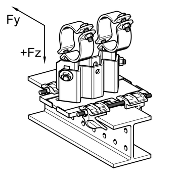
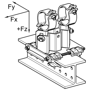
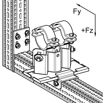
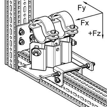
The tests for lifting forces - Fz were performed using a combination of a pipe shoe LC - HV an a guiding or fixed points sets. This results in the values for - Fz in the following combinations:
| - | beam connection with the FS guiding set or the XS fixed point set. |
| - | Connection to siFramo with the guiding bracket FW F or the fixed point bracket XW F |
Further statical product datas are available on request.
Material-dependent temperature correction values (k)
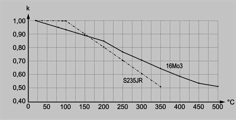
| Temperature | 16Mo3 | S235JR |
|---|---|---|
| 20°C | 1.00 | 1.00 |
| 80°C | 0.95 | 1.00 |
| 100°C | 0.93 | 1.00 |
| 150°C | 0.89 | 0.90 |
| 200°C | 0.85 | 0.81 |
| 250°C | 0.77 | 0.71 |
| 300°C | 0.71 | 0.61 |
| 350°C | 0.64 | 0.52 |
| 400°C | 0.58 | - |
| 450°C | 0.53 | - |
| 500°C | 0.51 | - |
| LC - HV | D mm | DN | Fx [kN] | Fy [kN] | + Fz [kN] | - Fz FS 80/120 [kN] | - Fz FW F 80 [kN] | - Fz XS 80/120 [kN] | - Fz XW F 80 [kN] | |
|---|---|---|---|---|---|---|---|---|---|---|
| 90 | 14-18 | 11.4 | 6.4 | 17 | 14 | 6.1 | 17 | 17 | ||
| 90 | 18-22 | 15 | 11.4 | 6.4 | 17 | 14 | 6.1 | 17 | 17 | |
| 90 | 23-27 | 20 | 11.4 | 6.4 | 17 | 14 | 6.1 | 17 | 17 | |
| 90 | 26-30 | 11.4 | 6.4 | 17 | 14 | 6.1 | 17 | 17 | ||
| 90 | 30-34 | 25 | 11.4 | 6.4 | 17 | 14 | 6.1 | 17 | 17 | |
| 90 | 35-39 | 11.4 | 6.3 | 17 | 14 | 6.1 | 17 | 17 | ||
| 90 | 40-44 | 32 | 11.3 | 6.2 | 17 | 14 | 6.1 | 17 | 17 | |
| 90 | 45-49 | 40 | 11.3 | 6.1 | 17 | 14 | 6.1 | 17 | 17 | |
| 90 | 50-54 | 11.3 | 6.0 | 17 | 14 | 6.1 | 17 | 17 | ||
| 90 | 55-59 | 11.2 | 6.0 | 17 | 14 | 6.1 | 17 | 17 | ||
| 90 | 57-61 | 50 | 11.2 | 5.9 | 17 | 14 | 6.1 | 17 | 17 | |
| 90 | 62-66 | 11.2 | 5.8 | 17 | 14 | 6.1 | 17 | 17 | ||
| 90 | 67-71 | 11.2 | 5.8 | 17 | 14 | 6.1 | 17 | 17 | ||
| 90 | 72-77 | 65 | 11.1 | 5.6 | 17 | 14 | 6.1 | 17 | 17 | |
| 90 | 78-83 | 11.1 | 5.5 | 17 | 14 | 6.1 | 17 | 17 | ||
| 90 | 84-89 | 80 | 11.1 | 5.4 | 17 | 14 | 6.1 | 17 | 17 | |
| 90 | 89-95 | 11.0 | 5.3 | 17 | 14 | 6.1 | 17 | 17 | ||
| 90 | 96-102 | 11.0 | 5.2 | 17 | 14 | 6.1 | 17 | 17 | ||
| 90 | 102-109 | 10.9 | 5.1 | 17 | 14 | 6.1 | 17 | 17 | ||
| 90 | 109-115 | 100 | 10.9 | 5.0 | 17 | 14 | 6.1 | 17 | 17 | |
| 90 | 115-122 | 10.9 | 4.9 | 17 | 14 | 6.1 | 17 | 17 | ||
| 90 | 122-128 | 10.8 | 4.8 | 17 | 14 | 6.1 | 17 | 17 | ||
| 90 | 128-134 | 10.8 | 4.7 | 17 | 14 | 6.1 | 17 | 17 | ||
| 90 | 134-140 | 125 | 10.8 | 4.6 | 17 | 14 | 6.1 | 17 | 17 | |
| 90 | 140-146 | 10.7 | 4.4 | 17 | 14 | 6.1 | 17 | 17 | ||
| 90 | 146-152 | 10.7 | 4.3 | 17 | 14 | 6.1 | 17 | 17 | ||
| 90 | 152-158 | 10.6 | 4.2 | 17 | 14 | 6.1 | 17 | 17 | ||
| 90 | 157-163 | 10.6 | 4.2 | 17 | 14 | 6.1 | 17 | 17 | ||
| 90 | 163-169 | 150 | 10.6 | 4.0 | 17 | 14 | 6.1 | 17 | 17 | |
| 90 | 168-174 | 10.5 | 4.0 | 17 | 14 | 6.1 | 17 | 17 | ||
| 90 | 174-180 | 10.5 | 3.9 | 17 | 14 | 6.1 | 17 | 17 | ||
| 90 | 181-187 | 10.5 | 3.7 | 17 | 14 | 6.1 | 17 | 17 | ||
| 90 | 188-194 | 10.4 | 3.6 | 17 | 14 | 6.1 | 17 | 17 | ||
| 90 | 194-200 | 10.4 | 3.5 | 17 | 14 | 6.1 | 17 | 17 | ||
| 90 | 201-207 | 10.3 | 3.4 | 17 | 14 | 6.1 | 17 | 17 | ||
| 90 | 208-214 | 10.3 | 3.3 | 17 | 14 | 6.1 | 17 | 17 | ||
| 90 | 215-221 | 200 | 10.3 | 3.1 | 17 | 14 | 6.1 | 17 | 17 | |
| 90 | 222-229 | 10.2 | 3.0 | 17 | 14 | 6.1 | 17 | 17 | ||
| 90 | 230-237 | 10.2 | 2.9 | 17 | 14 | 6.1 | 17 | 17 | ||
| 90 | 238-245 | 10.1 | 2.7 | 17 | 14 | 6.1 | 17 | 17 | ||
| 90 | 246-254 | 10.1 | 2.6 | 17 | 14 | 6.1 | 17 | 17 | ||
| 90 | 255-262 | 10.0 | 2.4 | 17 | 14 | 6.1 | 17 | 17 | ||
| 90 | 259-266 | 10.0 | 2.4 | 17 | 14 | 6.1 | 17 | 17 | ||
| 90 | 266-273 | 250 | 9.9 | 2.2 | 17 | 14 | 6.1 | 17 | 17 | |
| 90 | 274-282 | 9.9 | 2.1 | 17 | 14 | 6.1 | 17 | 17 | ||
| 90 | 283-291 | 9.8 | 1.9 | 17 | 14 | 6.1 | 17 | 17 | ||
| 90 | 292-300 | 9.8 | 1.8 | 17 | 14 | 6.1 | 17 | 17 | ||
| 90 | 301-309 | 9.7 | 1.6 | 17 | 14 | 6.1 | 17 | 17 | ||
| 90 | 310-317 | 9.7 | 1.5 | 17 | 14 | 6.1 | 17 | 17 | ||
| 90 | 317-324 | 300 | 9.6 | 1.4 | 17 | 14 | 6.1 | 17 | 17 |
Basis for assessment EC 3, working loads for Supports in delivery status
Sliding Support LC - HV + Guiding Set FS resp. Fixed Point Set XS
Sliding Support LC - HV + Guiding Bracket FW F 80 resp. Fixed Point Bracket XW F 80
| LC - HV | D [mm] | DN | Fx [kN] | Fy [kN] | + Fz [kN] | - Fz FS 80/120 [kN] | - Fz FW F 80 [kN] | - Fz XS 80/120 [kN] | - Fz XW F 80 [kN] | |
|---|---|---|---|---|---|---|---|---|---|---|
| 150 | 14-18 | 8.6 | 4.7 | 17 | 14 | 6.1 | 17 | 17 | ||
| 150 | 18-22 | 15 | 8.6 | 4.7 | 17 | 14 | 6.1 | 17 | 17 | |
| 150 | 23-27 | 20 | 8.6 | 4.7 | 17 | 14 | 6.1 | 17 | 17 | |
| 150 | 26-30 | 8.6 | 4.7 | 17 | 14 | 6.1 | 17 | 17 | ||
| 150 | 30-34 | 25 | 8.6 | 4.7 | 17 | 14 | 6.1 | 17 | 17 | |
| 150 | 35-39 | 8.6 | 4.7 | 17 | 14 | 6.1 | 17 | 17 | ||
| 150 | 40-44 | 32 | 8.6 | 4.6 | 17 | 14 | 6.1 | 17 | 17 | |
| 150 | 45-49 | 40 | 8.6 | 4.6 | 17 | 14 | 6.1 | 17 | 17 | |
| 150 | 50-54 | 8.5 | 4.5 | 17 | 14 | 6.1 | 17 | 17 | ||
| 150 | 55-59 | 8.5 | 4.4 | 17 | 14 | 6.1 | 17 | 17 | ||
| 150 | 57-61 | 50 | 8.5 | 4.4 | 17 | 14 | 6.1 | 17 | 17 | |
| 150 | 62-66 | 8.5 | 4.4 | 17 | 14 | 6.1 | 17 | 17 | ||
| 150 | 67-71 | 8.5 | 4.3 | 17 | 14 | 6.1 | 17 | 17 | ||
| 150 | 72-77 | 65 | 8.5 | 4.2 | 17 | 14 | 6.1 | 17 | 17 | |
| 150 | 78-83 | 8.5 | 4.2 | 17 | 14 | 6.1 | 17 | 17 | ||
| 150 | 84-89 | 8.5 | 4.1 | 17 | 14 | 6.1 | 17 | 17 | ||
| 150 | 89-95 | 8.4 | 4.0 | 17 | 14 | 6.1 | 17 | 17 | ||
| 150 | 96-102 | 8.4 | 4.0 | 17 | 14 | 6.1 | 17 | 17 | ||
| 150 | 102-109 | 8.4 | 3.9 | 17 | 14 | 6.1 | 17 | 17 | ||
| 150 | 109-115 | 100 | 8.4 | 3.8 | 17 | 14 | 6.1 | 17 | 17 | |
| 150 | 115-122 | 8.4 | 3.7 | 17 | 14 | 6.1 | 17 | 17 | ||
| 150 | 122-128 | 8.4 | 3.7 | 17 | 14 | 6.1 | 17 | 17 | ||
| 150 | 128-134 | 8.3 | 3.6 | 17 | 14 | 6.1 | 17 | 17 | ||
| 150 | 134-140 | 125 | 8.3 | 3.5 | 17 | 14 | 6.1 | 17 | 17 | |
| 150 | 140-146 | 8.3 | 3.5 | 17 | 14 | 6.1 | 17 | 17 | ||
| 150 | 146-152 | 8.3 | 3.4 | 17 | 14 | 6.1 | 17 | 17 | ||
| 150 | 150-158 | 8.3 | 3.3 | 17 | 14 | 6.1 | 17 | 17 | ||
| 150 | 157-163 | 8.3 | 3.3 | 17 | 14 | 6.1 | 17 | 17 | ||
| 150 | 163-169 | 150 | 8.3 | 3.2 | 17 | 14 | 6.1 | 17 | 17 | |
| 150 | 168-174 | 8.2 | 3.2 | 17 | 14 | 6.1 | 17 | 17 | ||
| 150 | 174-180 | 8.2 | 3.1 | 17 | 14 | 6.1 | 17 | 17 | ||
| 150 | 181-187 | 8.2 | 3.0 | 17 | 14 | 6.1 | 17 | 17 | ||
| 150 | 188-194 | 8.2 | 3.0 | 17 | 14 | 6.1 | 17 | 17 | ||
| 150 | 194-200 | 8.2 | 2.9 | 17 | 14 | 6.1 | 17 | 17 | ||
| 150 | 201-207 | 8.2 | 2.8 | 17 | 14 | 6.1 | 17 | 17 | ||
| 150 | 208-214 | 8.2 | 2.7 | 17 | 14 | 6.1 | 17 | 17 | ||
| 150 | 215-221 | 200 | 8.1 | 2.7 | 17 | 14 | 6.1 | 17 | 17 | |
| 150 | 222-229 | 8.1 | 2.6 | 17 | 14 | 6.1 | 17 | 17 | ||
| 150 | 230-237 | 8.1 | 2.5 | 17 | 14 | 6.1 | 17 | 17 | ||
| 150 | 238-245 | 8.1 | 2.4 | 17 | 14 | 6.1 | 17 | 17 | ||
| 150 | 246-254 | 8.1 | 2.3 | 17 | 14 | 6.1 | 17 | 17 | ||
| 150 | 255-262 | 8.0 | 2.2 | 17 | 14 | 6.1 | 17 | 17 | ||
| 150 | 259-266 | 8.0 | 2.2 | 17 | 14 | 6.1 | 17 | 17 | ||
| 150 | 266-273 | 250 | 8.0 | 2.1 | 17 | 14 | 6.1 | 17 | 17 | |
| 150 | 274-282 | 8.0 | 2.0 | 17 | 14 | 6.1 | 17 | 17 | ||
| 150 | 283-291 | 8.0 | 1.9 | 17 | 14 | 6.1 | 17 | 17 | ||
| 150 | 292-300 | 7.9 | 1.8 | 17 | 14 | 6.1 | 17 | 17 | ||
| 150 | 301-309 | 7.9 | 1.7 | 17 | 14 | 6.1 | 17 | 17 | ||
| 150 | 310-317 | 7.9 | 1.6 | 17 | 14 | 6.1 | 17 | 17 | ||
| 150 | 317-324 | 300 | 7.9 | 1.5 | 17 | 14 | 6.1 | 17 | 17 |
Basis for assessment EC 3, working loads for Supports in delivery status
Sliding Support LC - HV + Guiding Set FS resp. Fixed Point Set XS
Sliding Support LC - HV + Guiding Bracket FW F 80 resp. Fixed Point Bracket XW F 80
| LC - HV | D [mm] | DN | Fx [kN] | Fy [kN] | + Fz [kN] | - Fz FS 80/120 [kN] | - Fz FW F 80 [kN] | - Fz XS 80/120 [kN] | - Fz XW F 80 [kN] | |
|---|---|---|---|---|---|---|---|---|---|---|
| 200 | 14-18 | 7.4 | 5.0 | 17 | 14 | 6.1 | 17 | 17 | ||
| 200 | 18-22 | 15 | 7.4 | 5.0 | 17 | 14 | 6.1 | 17 | 17 | |
| 200 | 23-27 | 20 | 7.4 | 5.0 | 17 | 14 | 6.1 | 17 | 17 | |
| 200 | 26-30 | 7.4 | 5.0 | 17 | 14 | 6.1 | 17 | 17 | ||
| 200 | 30-34 | 25 | 7.4 | 5.0 | 17 | 14 | 6.1 | 17 | 17 | |
| 200 | 35-39 | 7.4 | 4.9 | 17 | 14 | 6.1 | 17 | 17 | ||
| 200 | 40-44 | 32 | 7.4 | 4.9 | 17 | 14 | 6.1 | 17 | 17 | |
| 200 | 45-49 | 40 | 7.4 | 4.8 | 17 | 14 | 6.1 | 17 | 17 | |
| 200 | 50-54 | 7.4 | 4.8 | 17 | 14 | 6.1 | 17 | 17 | ||
| 200 | 55-59 | 7.4 | 4.7 | 17 | 14 | 6.1 | 17 | 17 | ||
| 200 | 57-61 | 50 | 7.4 | 4.7 | 17 | 14 | 6.1 | 17 | 17 | |
| 200 | 62-66 | 7.3 | 4.6 | 17 | 14 | 6.1 | 17 | 17 | ||
| 200 | 67-71 | 7.3 | 4.6 | 17 | 14 | 6.1 | 17 | 17 | ||
| 200 | 72-77 | 65 | 7.3 | 4.5 | 17 | 14 | 6.1 | 17 | 17 | |
| 200 | 78-83 | 7.3 | 4.4 | 17 | 14 | 6.1 | 17 | 17 | ||
| 200 | 84-89 | 80 | 7.3 | 4.4 | 17 | 14 | 6.1 | 17 | 17 | |
| 200 | 89-95 | 7.3 | 4.3 | 17 | 14 | 6.1 | 17 | 17 | ||
| 200 | 96-102 | 7.3 | 4.2 | 17 | 14 | 6.1 | 17 | 17 | ||
| 200 | 102-109 | 7.3 | 4.1 | 17 | 14 | 6.1 | 17 | 17 | ||
| 200 | 109-115 | 100 | 7.3 | 4.1 | 17 | 14 | 6.1 | 17 | 17 | |
| 200 | 115-122 | 7.3 | 4.0 | 17 | 14 | 6.1 | 17 | 17 | ||
| 200 | 122-128 | 7.3 | 3.9 | 17 | 14 | 6.1 | 17 | 17 | ||
| 200 | 128-134 | 7.2 | 3.9 | 17 | 14 | 6.1 | 17 | 17 | ||
| 200 | 134-140 | 125 | 7.2 | 3.8 | 17 | 14 | 6.1 | 17 | 17 | |
| 200 | 140-146 | 7.2 | 3.7 | 17 | 14 | 6.1 | 17 | 17 | ||
| 200 | 146-152 | 7.2 | 3.6 | 17 | 14 | 6.1 | 17 | 17 | ||
| 200 | 152-158 | 7.2 | 3.6 | 17 | 14 | 6.1 | 17 | 17 | ||
| 200 | 157-163 | 7.2 | 3.5 | 17 | 14 | 6.1 | 17 | 17 | ||
| 200 | 163-169 | 150 | 7.2 | 3.5 | 17 | 14 | 6.1 | 17 | 17 | |
| 200 | 168-174 | 7.2 | 3.4 | 17 | 14 | 6.1 | 17 | 17 | ||
| 200 | 174-180 | 7.2 | 3.3 | 17 | 14 | 6.1 | 17 | 17 | ||
| 200 | 181-187 | 7.2 | 3.2 | 17 | 14 | 6.1 | 17 | 17 | ||
| 200 | 188-194 | 7.2 | 3.2 | 17 | 14 | 6.1 | 17 | 17 | ||
| 200 | 194-200 | 7.1 | 3.1 | 17 | 14 | 6.1 | 17 | 17 | ||
| 200 | 201-207 | 7.1 | 3.0 | 17 | 14 | 6.1 | 17 | 17 | ||
| 200 | 208-214 | 7.1 | 2.9 | 17 | 14 | 6.1 | 17 | 17 | ||
| 200 | 215-221 | 200 | 7.1 | 2.9 | 17 | 14 | 6.1 | 17 | 17 | |
| 200 | 222-229 | 7.1 | 2.8 | 17 | 14 | 6.1 | 17 | 17 | ||
| 200 | 230-237 | 7.1 | 2.7 | 17 | 14 | 6.1 | 17 | 17 | ||
| 200 | 238-245 | 7.1 | 2.6 | 17 | 14 | 6.1 | 17 | 17 | ||
| 200 | 246-254 | 7.1 | 2.5 | 17 | 14 | 6.1 | 17 | 17 | ||
| 200 | 255-262 | 7.0 | 2.4 | 17 | 14 | 6.1 | 17 | 17 | ||
| 200 | 259-266 | 7.0 | 2.3 | 17 | 14 | 6.1 | 17 | 17 | ||
| 200 | 266-273 | 250 | 7.0 | 2.3 | 17 | 14 | 6.1 | 17 | 17 | |
| 200 | 274-282 | 7.0 | 2.2 | 17 | 14 | 6.1 | 17 | 17 | ||
| 200 | 283-291 | 7.0 | 2.1 | 17 | 14 | 6.1 | 17 | 17 | ||
| 200 | 292-300 | 7.0 | 2.0 | 17 | 14 | 6.1 | 17 | 17 | ||
| 200 | 301-309 | 7.0 | 1.8 | 17 | 14 | 6.1 | 17 | 17 | ||
| 200 | 310-317 | 7.0 | 1.8 | 17 | 14 | 6.1 | 17 | 17 | ||
| 200 | 317-324 | 300 | 7.0 | 1.7 | 17 | 14 | 6.1 | 17 | 17 |
Basis for assessment EC 3, working loads for Supports in delivery status
Sliding Support LC - HV + Guiding Set FS resp. Fixed Point Set XS
Sliding Support LC - HV + Guiding Bracket FW F 80 resp. Fixed Point Bracket XW F 80